
Sensor・Amplifier・Interface
Articles
The papers are linked to CiNii, a service of National Institute of Informatics in Japan.
Also, they can be searched with J-STAGE to browse.
Technical Information
Precautions
General precautions for our 3-axis Force Sensors
- Do not drop or give a shock to the sensor.
- Do not disassemble the sensor or it may be beyond repair.
- Do not expose the sensor to dust or water (waterdrop).
- Our sensor is designed to detect shear force and three components of force applied to the pressure receiving part. Be careful not to apply rotation or bending moment to the sensor.
<The below table shows a guide of allowable moment ranges>
Note: Use as a rough indication. The sensitivity of the sensor is not guaranteed under the situation where moment can be applied.
| Model | Mx(N・m) | My(N・m) | Mz(N・m) |
|---|---|---|---|
| USL06-H5-50N | 0.7 | 0.7 | 0.4 |
| USL06-H5-100N | 0.7 | 0.7 | 0.4 |
| USL06-H5-200N | 1 | 1 | 0.4 |
| USL06-H5-500N | 2 | 2 | 0.7 |
| USL08-H6-2KN | 5 | 5 | 5 |
| TL3B04-5KN | 70 | 70 | 90 |
- The guaranteed temperature range incluses daily temperature variation. However, be careful not to place the sensor under direct sunlight or it may affect the sensitivity.
- Do not pull, pintch or step on a cable. Do not bend the cable near the sensor body.
- Do not apply excessive load over the allowable load capacity (120% of rated capacity) when mounting.
Precautions for USL06 series

- Fix four locations with M2 hexagon socket head bolts.
An uneven surface affects the characteristic and may cause a breakage.
The flatness of 0.01mm or below is recommended for a mounting surface of 20mm x 20mm. - Use a M3 screw hole at the center of the sensor to fix a specimen.
Make sure to use a screw with the length of 4mm or shorter from the pressure receiver surface (Φ6). Using a screw longer than 4.5mm may damage a sensor.
Do not overtighten a screw or it may damage the sensor since screwing applies rotation moment. Carefully tighten a M3 screw with appropriate force so that it does not become loose.
<Recommended ranges of tightening torque>
| Model | Recommended tightening torque |
|---|---|
| USL06-H5-50N | 40N・cm or below |
| USL06-H5-100N | 40N・cm or below |
| USL06-H5-200N | 40N・cm or below |
| USL06-H5-500N | 70N・cm or below |
Setup procedure [USL06 → DSA-03A → DSS300-U]
Precautions for setup.
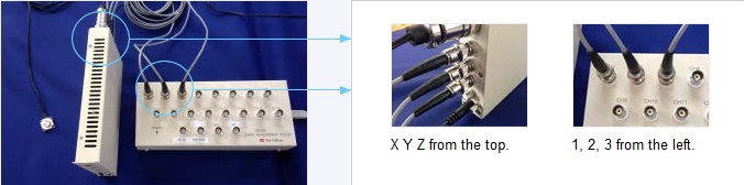
Connect cables; X: ch.1 Y:ch.2 Z: ch.3.
(Connect cables in the same way for following sensors; X: ch.4, Y:ch.5, Z: ch.6….).
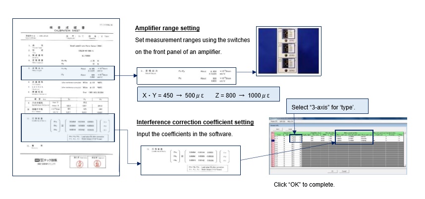
The below 2 settings are required. Refer to the inspection report of the sensor.
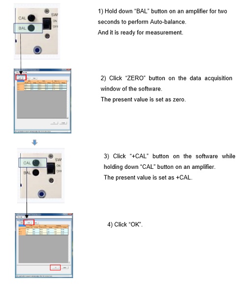
Perform zeroing (auto-balance) and calibration.
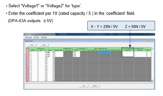
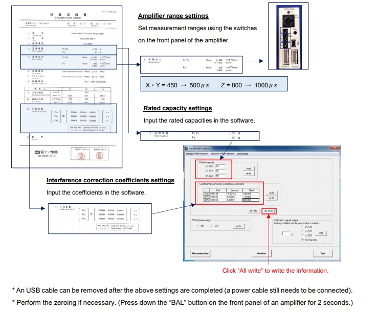
Setup procedure [ USL06 → DPA-03A ]
Sensor [USL06]- Amplifier [DPA-03A]
Install the DPA-03A control software in a computer before the setup.
Then connect the DPA-03A and a computer with a USB cable (a driver must be installed when using for the first time).
Turn on the power and start the software.
Follow the below steps to set analog output, voltage (V) = sensor rated output.
The below settings are required. Refer to the inspection report of the sensor.
When using our DSS300 for measurement software.